Fox® Overhead Traveling Grinder

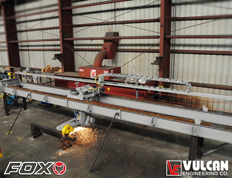
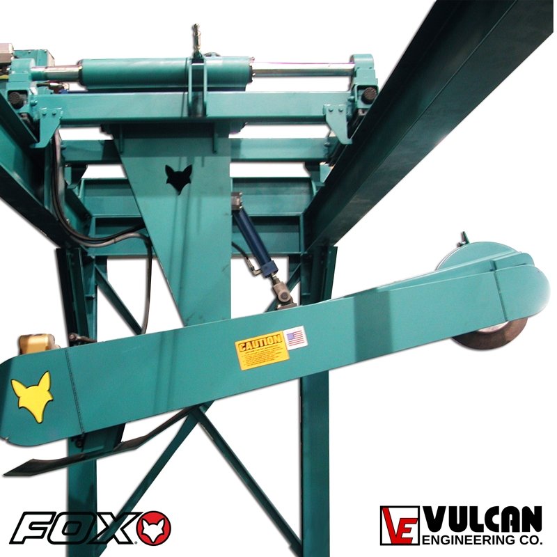
Fox® Overhead Traveling Grinder for spot grinding and ingot clean-up. This system is remotely operated reducing fatigue to the operator. With the primary controls at the operator’s fingertips and his ability to operate the system in a standing position, his fatigue will be significantly reduced when compared with the swing frame setup. The wireless control station is designed for ease of operation, as well as allowing the operator to move along the work piece for close visual inspection of areas being ground and yet be isolated from the machine eliminating transmission of vibration through handlebars. The controls will allow “feathering” of the areas being spot ground.

Fox® Overhead Traveling Grinder for spot grinding and ingot clean-up. This system is remotely operated reducing fatigue to the operator. With the primary controls at the operator’s fingertips and his ability to operate the system in a standing position, his fatigue will be significantly reduced when compared with the swing frame setup. The wireless control station is designed for ease of operation, as well as allowing the operator to move along the work piece for close visual inspection of areas being ground and yet be isolated from the machine eliminating transmission of vibration through handlebars. The controls will allow “feathering” of the areas being spot ground.

The system includes the following:
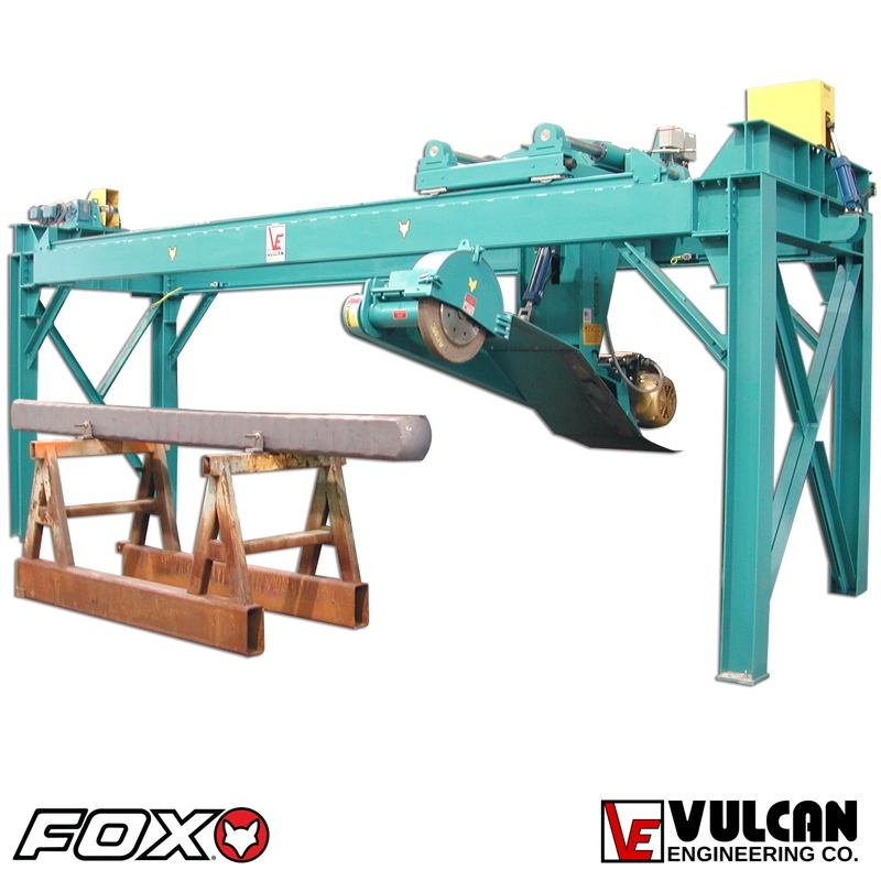
• Free standing bridge crane and rail system for support of the grinder.
• Traveling base to support the carriage and grinder. The base is used for left/right travel.
• Carriage for the in/out movement of the grinder.
• Cable drive for left/right movement
• Inverted grinder.
• Hydraulic power unit is located at floor level on one end of the rail support for ease of access for maintenance. Pressure and tank lines run through a power track connecting to a valve manifold on the carriage.
• Electrical system including controls located at end of structure.
• Both the electrical panel and the hydraulic power unit will be located within 10 feet of the end of the structure.

Grinder Head

Horizontal Left/Right Travel of Grinder: 15 ft (4.5 m) Horizontal Stroke of Grinder Head: 24 in (609 mm); Vertical Stroke of Grinder Head: Approximately 3 ft

Grinding Wheel

Size: 24 in x 2 in to 3 in x 12 in (610mm x 50mm to 76mm x 305mm) Speed: 12,500 SFPM @ 24 in (610mm) Force: 0-500 lbs (227 kgs) Drive: 50 HP (37 kws) @ 1800 RPM

Grinding Angle

(Wheel to Work) 90°

  • Free standing bridge crane and rail system for support of the grinder.
  • Traveling base to support the carriage and grinder. The base is used for left/right travel.
  • Carriage for the in/out movement of the grinder.
  • Cable drive for left/right movement
  • Inverted grinder.
  • Hydraulic power unit is located at floor level on one end of the rail support for ease of access for maintenance. Pressure and tank lines run through a power track connecting to a valve manifold on the carriage.
  • Electrical system including controls located at end of structure.
  • Both the electrical panel and the hydraulic power unit will be located within 10 feet of the end of the structure.
Download Application Data Sheet for Metal Conditioning


If you are unable to watch this video because of software or network restrictions, please contact us. We would be glad to send you a copy of the video. For more information Click Here >>